Mecanum Car
My son loves cars. Our favorite part of Discovery Day at Oracle Park was the Robot Zoo. It showcased dozens of robots built local robotics clubs. All the robots used mecanum wheels. Building a mecanum car to drive around our living room seemed like a fun idea.
Parts
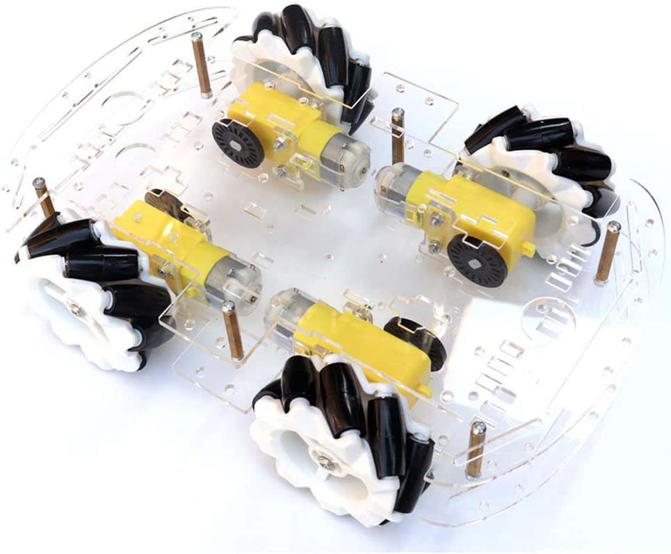
My online searching came up with this basic Mecanum kit for $36.99. I tried searching AliExpress, but for a single order, including shipping, Amazon Prime had the best deal. Other BOM items were:
- 12 pack of STMicroelectronics TIP 120 on Amazon Prime. Digi-Key had terrible inventory of TIP 120s when I looked.
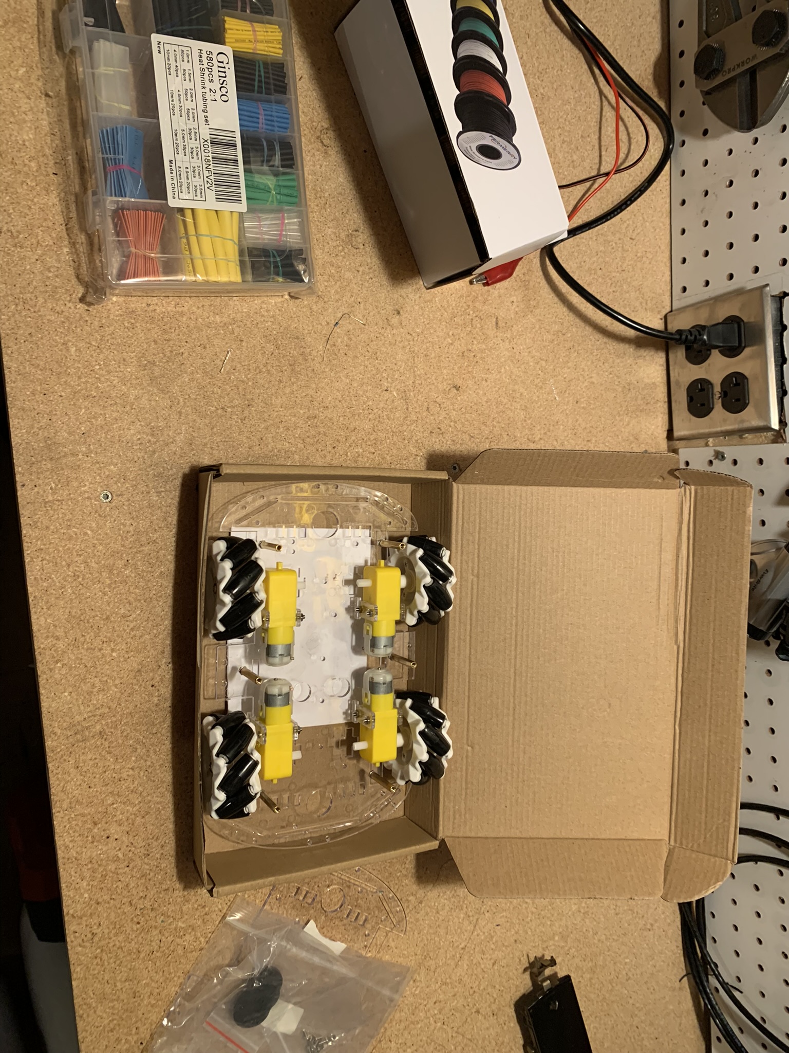
- 26 AWG hook up wire also on Amazon.
- Assorted Heat Shrink Tubing to keep wires organized. Yet again, on Amazon.
The selection and prices on Amazon surprised me.
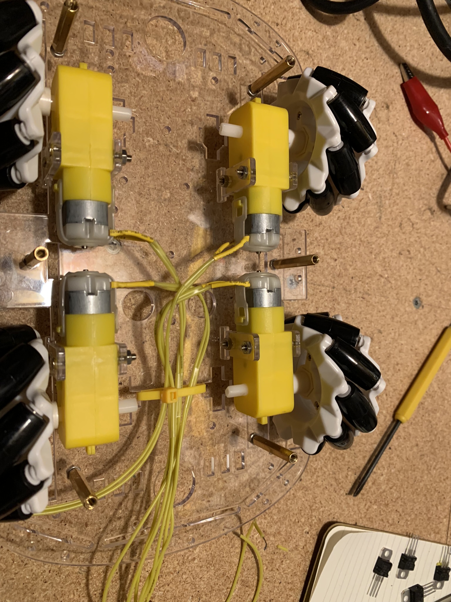
Assembly
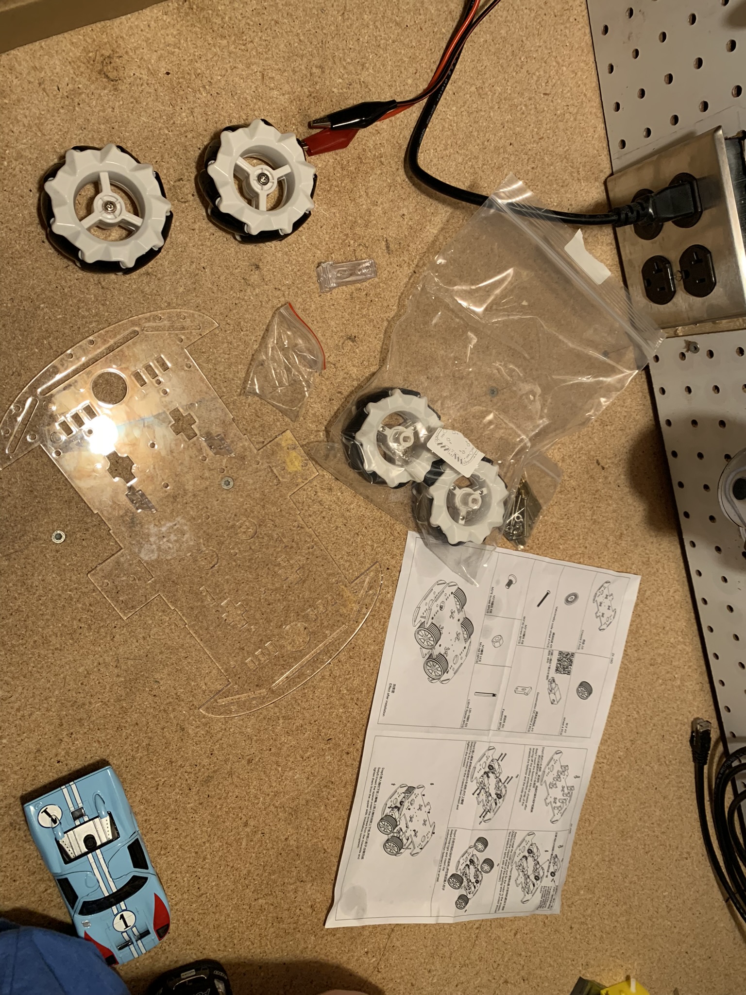
Assembling the car is straightforward. This was a fun project with my son. Pre-cut acrylic parts slot together, held in place by metal screws and nuts. There are lots of pre-cut holes to mount sensors, electronics, etc.
Wiring
The motors in the mecanum car kit have short copper leads. I soldered two wires onto each motor. I added heat shrink tubing around each solder joint for strength and electrical insulation. This part wasn’t too complex, just laborious.
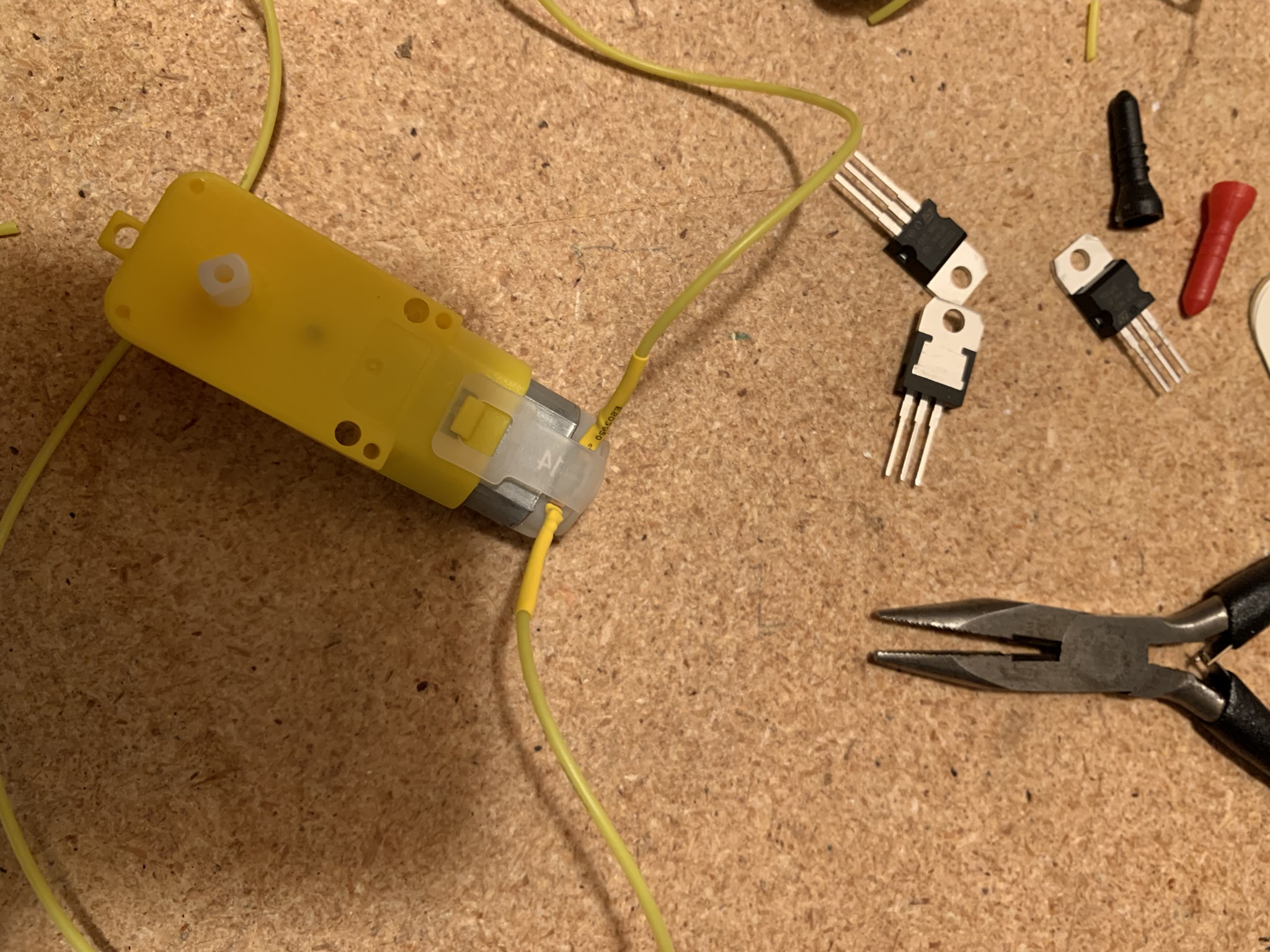
Driving Motors
I was initially thinking of using TIP-120s to drive the motors, but I need the ability to drive the motors forward and back. H-Bridges seemed like a perfect solution. ITP has a useful tutorial on how to drive a motor in a microcrontroller using an H-Bridge. I ended up purchasing the Adafruit L9110H H-Bridge and following their tutorial.
Following the tutorial worked fine, and I got all four wheels moving off of a power supply easily.
Systems Diagram
The plan for the entire system is in this basic MS Paint diagram: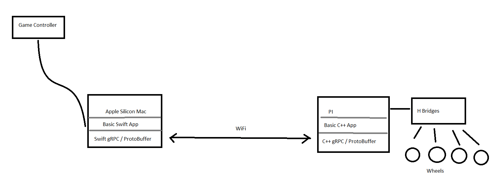
GRPC
The first step of the controls software was setting up a GRPC connection between the PI car and a desktop computer. The final plan is to use a USB GameStop XBox controller to control the car. The first step is to get a console application on a Ubuntu desktop talking to the Pi over GRPC.
Building and installing GRPC on the Pi was somewhat straightforward according to this tutorial: https://grpc.io/docs/languages/cpp/basics/ though there were some quirks:
- Building GRPC worked fine with -j4, but when linking the examples, I got a link error running -j4 (ld terminated with signal 9), which worked fine with no multithreading (maybe something to do with running out of memory?). Basically you have to build the projects with “make” not “make -j4.
- ifconfig wasn’t working, or maybe not installed on Raspian. I have to check the local IP with hostname -I .
- You have to open a gRPC port, in my case 50051. The easiest way to open it was with UncomplicatedFirewall - ufw. This initially worked fine with a simple “sudo ufw allow 50051” and “sudo ufw enable”. However, I forgot to open port 22 after installing ufw. This meant I mysteriously wasn’t able to SSH back into the Pi when I went back to work in the evening. The only way to get ssh working again was to set up a monitor, keyboard, and mouse on my workbench, and run “sudo ufw allow 22” and “sudo ufw enable”
- gRPC by default builds all the libraries as static (.a files). I’m was trying to keep this project simple so am not using CMake or Bazel, building with a one-line shell command. gRPC generates over 112 libraries, and determining the correct order to include them as links (-l) in g++ was harder than I thought.
- Bazel seems to be a more modern build system. I was able to install bazel by building and installing from source from this helpful github project: https://github.com/koenvervloesem/bazel-on-arm/blob/master/README.md . Bazel built and installed fine on my Pi. Unfortunately, building gRPC with bazel ran into problems. Running ‘bazel build :all’ gave the error “ERROR: An error occurred during the fetch of repository ‘go_sdk’ Error in fail: unsupported platform linux_arm”
- I was able to use the gRPC CMake examples as a scaffold for the car server. After general cleanup, the only key change was adding the pigpio library to the target_link_libraries function in CMakeLists.txt
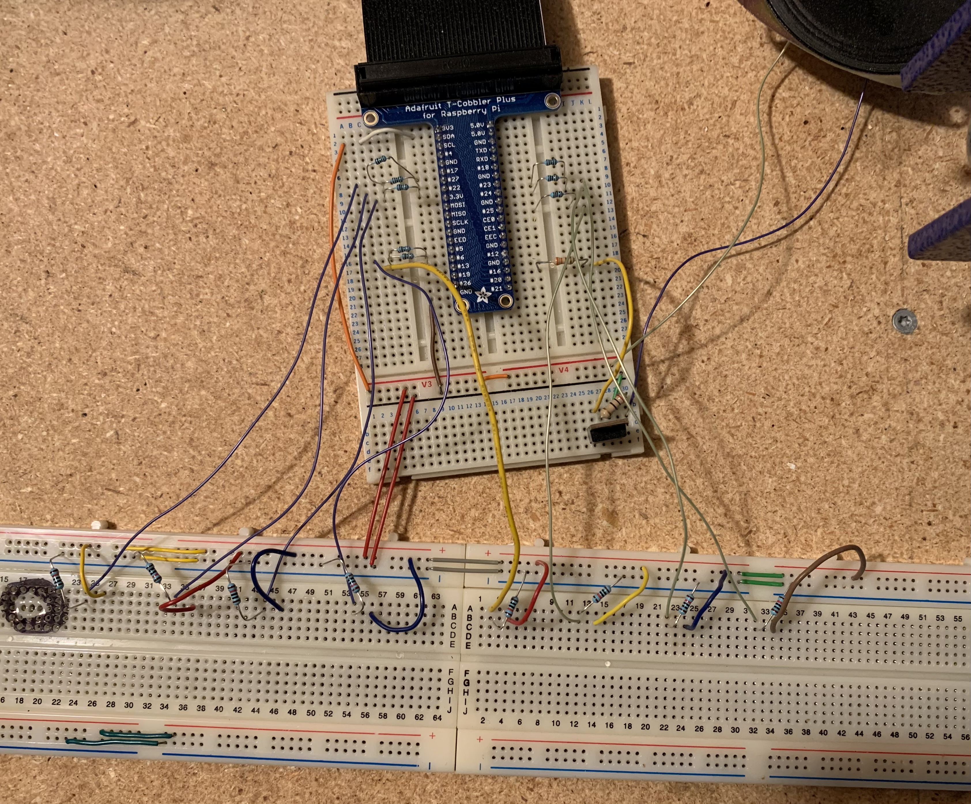
Testing
After getting the basic wiring working on a breadboard, I soldered the H-Bridge assembly onto a prototyping broadboard. For power, I bought a VGE 4000mAh battery pack on Amazon. I decided to drive the motors directly from the 5V pin on the Raspberry Pi. Without doing too thorough research, I found a three posts that suggest that if you keep the power under 1A you should be fine. Measuring the current of a full forward / reverse movement of the car showed the current to be about 0.62A.
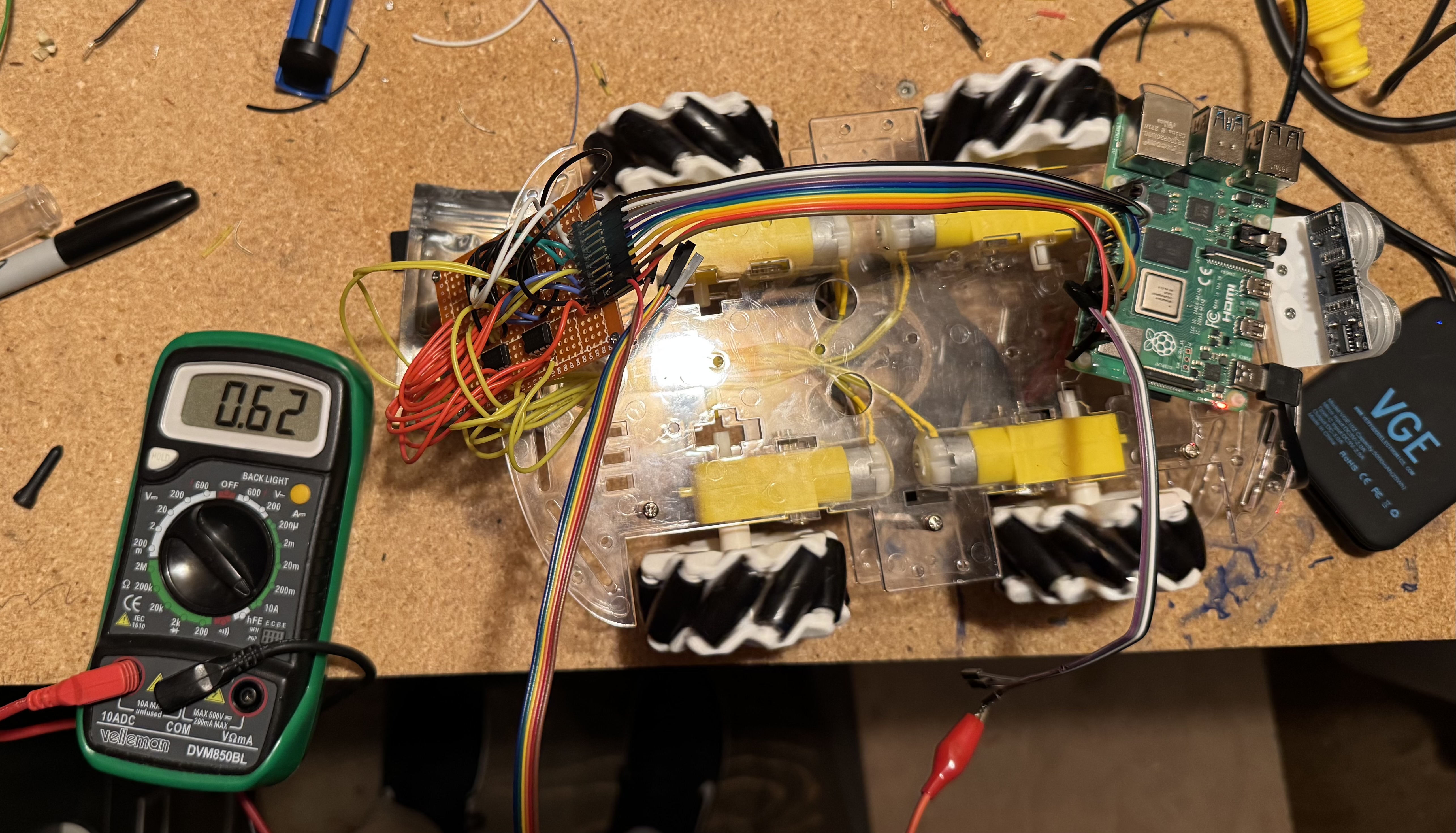
For this testing, the car is connected to Wifi, and the move instructions are being sent wirelessly. The car is now remote without a tether.
Enclosure
We build a simple enclosure for the car out of cardboard, and threw all the electronics in it.
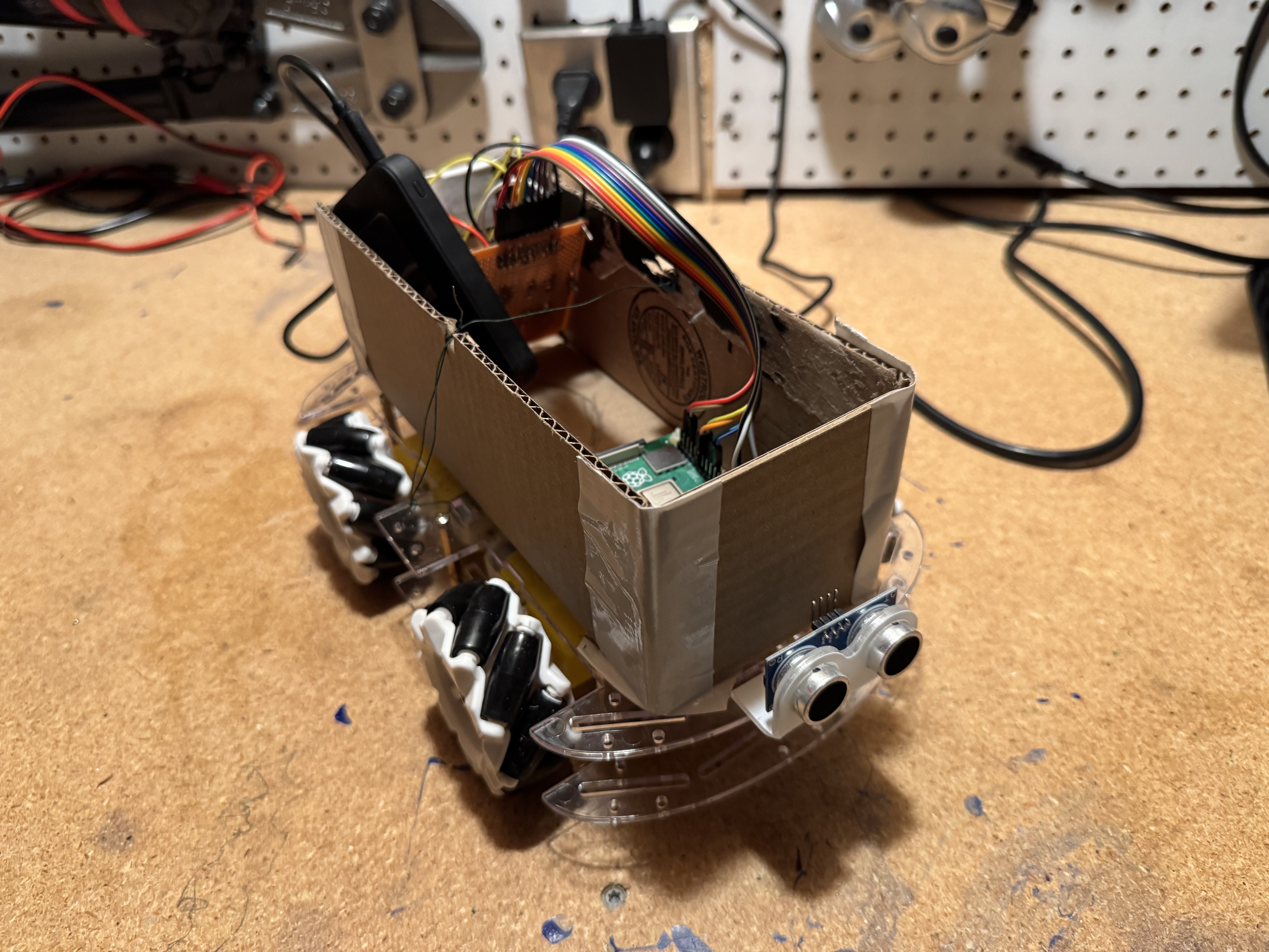
The video of it driving is on Youtube.
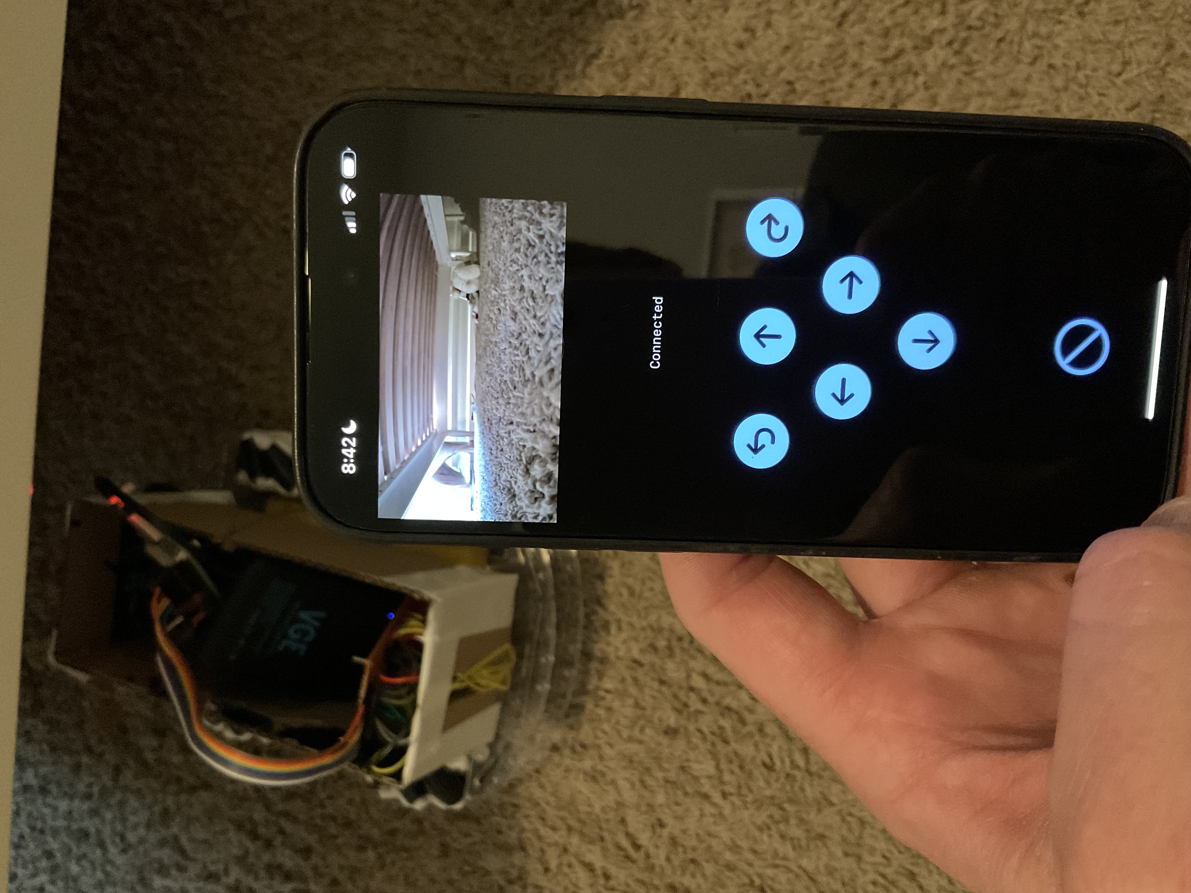
iOS App
I put together a quick iOS app to control the car. It communicates over gRPC (the car is the server, the app is the client). I also plugged in a web cam and hosted the video over gstreamer. The buttons send gRPC commands, and the webcam video is displayed in the app, allowing FPS-style driving. Below is the car exploring under my son’s bed.
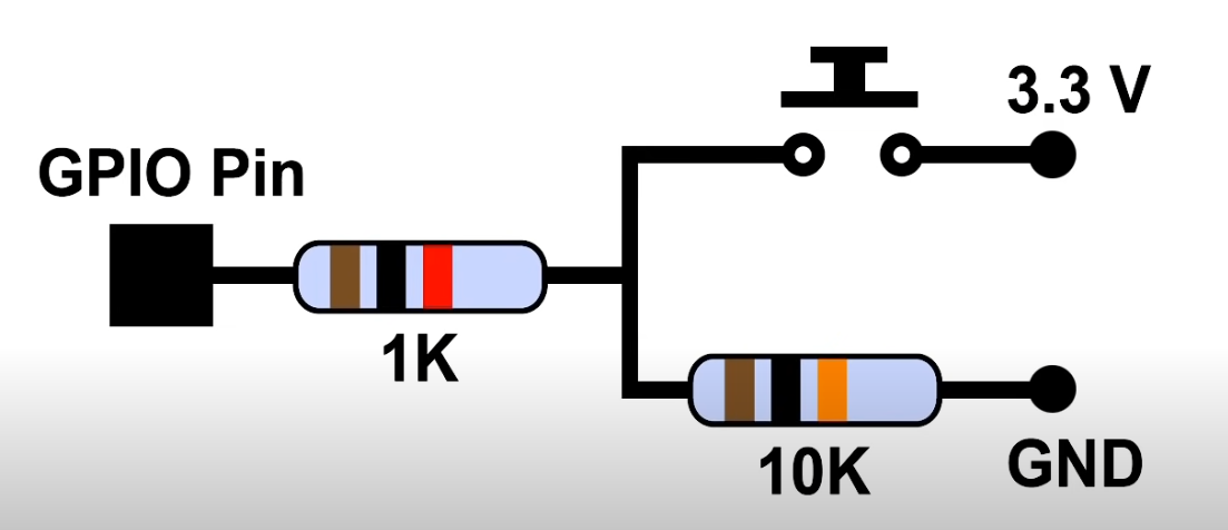

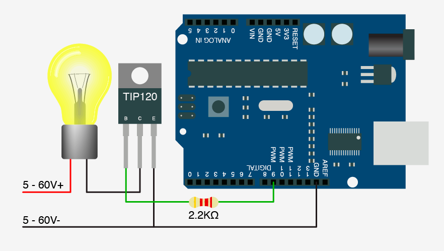 After quickly making the circuit, and playing around with resistor sizes, it worked great! I would recommend this