Toy Organ
After my company went bankrupt, I had a lot of time on my hands. I have a 3 year old son and was looking for projects to do with him. I dug up my old copies of Forrest M. Mims III Volume 1: Timer, Op Amp & Optoelectronic Circuits & Projects looking for projects. My son loves to sing, and enjoys playing with our toy xylophones. Mimm’s 555 Toy Organ on page 23 of V1 seemed like a perfect project to get him motivated about building electronics.
555 Toy Organ
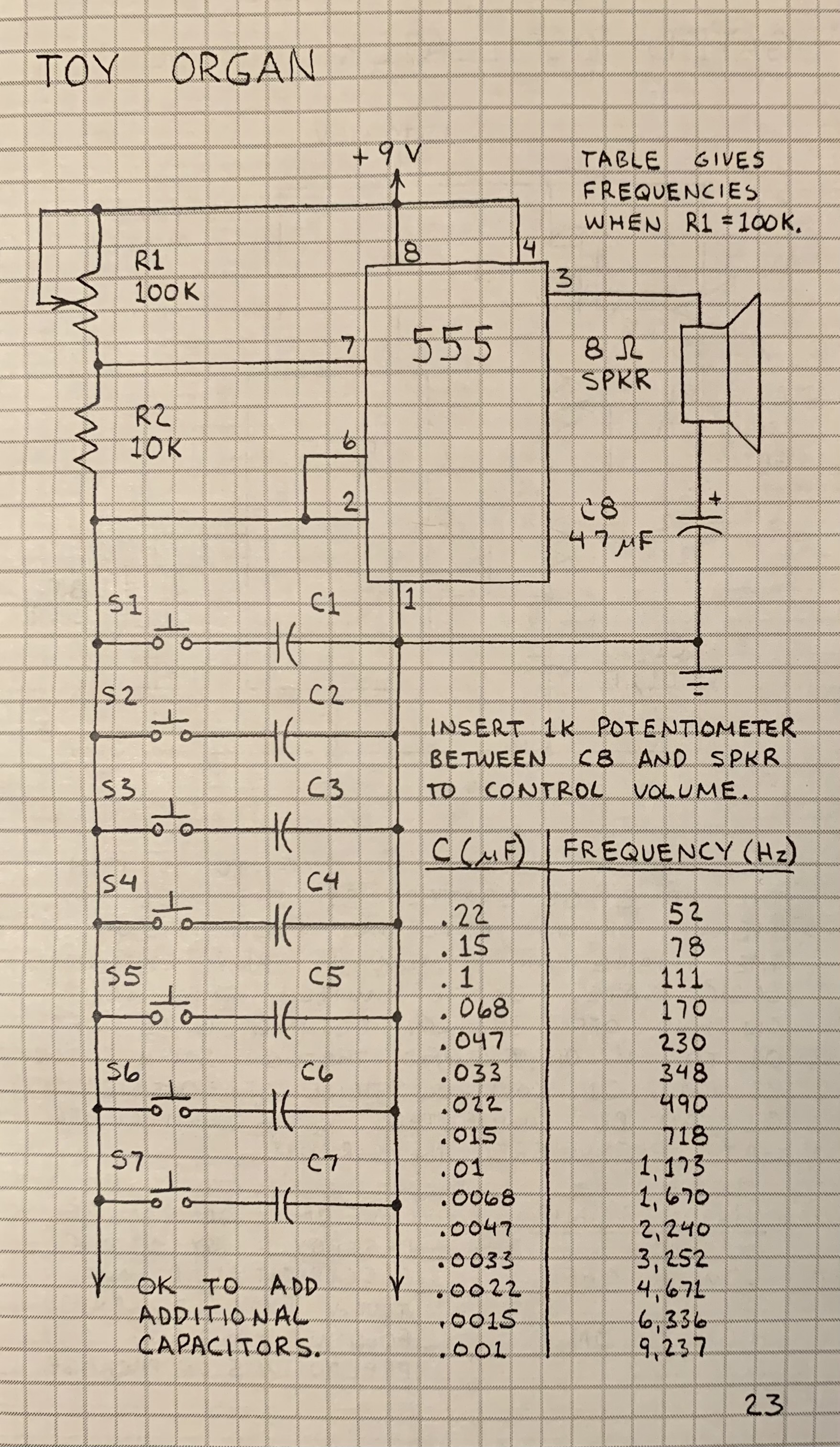
My initial approach was to attempt the project with the electronic components in my workshop. I had a 555 and 741 left over from previous projects. I didn’t have (or couldn’t find) the exact resistors and capacitors required, so I swapped out components I thought were close enough. Couldn’t I just swap out R1 100K variable resister with a 2K variable resistor, and make R2 a 333 OHM resistor?
It didn’t work.
Luckily I had a lot of time on my hands, so I headed over to Digi-Key and ordered all the proper materials as required by the schematics, and wired everything together.
It still didn’t work.
I didn’t own an oscilloscope, and don’t have a good sense of debugging circuits. I tried searching around on electronics forums, but the typical response to a post written in the last 15 years to someone asking “why doesn’t my 555 circuit work” is: “lol why are you still using a 555? There are much better ICs available.” I figured it would be easier to buy a Raspberry Pi, connect everything in software. At least I would have a better chance of debugging.
Raspberri Pi Toy Organ
As someone used to working with Arduinos and BASIC Stamps, Raspberri Pis are amazingly simple to use and program. Hats off to the Pi team!
My basic workflow was:
- Run Raspberry Pi OS on a 64GB SanDisk Extreme microSDXC
- Connect Pi to wired Ethernet on my workbench
- SSH into Pi, run GNU Screen + GNU Emacs 26
- Develop on my main computer with proper screen and keyboard
- Build and run GDB on the Pi directly
- Use a Pi Cobbler to connect GPIO to breadboard
I didn’t find a great entry point or tutorials on GPIO on a Raspberry Pi. pigpio seems to be the standard GPIO library for the Pi. Their website has a ton of great examples in C and C++.
My source code is here: https://github.com/ptierney/Pi/tree/master/toy_organ. It was in fact easier to program the logic for a basic organ with pigpio than debug my 555 circuit. The program generally speaking:
- Sets up pin modes (for input and output) and sets up callbacks for state changes on GPIO pins
- Waits on an infinite loop calling gpioTick()
- On a callback, set a gpioWave (a pigpio concept) with a pulse delay in microseconds. My current logic simply creates a square wave. It sets the speaker pin high for 1/2 the time in hertz of the tone. Technically my tones are off slightly because I approximated the hertz timing as integers, which is only true for A440. Wikipedia has a great list here that I referenced. It sounds good enough for my 3 year old though.
The wiring is straightforward. The Pi reads GPIO pins with a current-limiting pull-down circuit. Sound is output on a GPIO pin. I found this video incredibly helpful in describing the proper way to read a button on your Pi.
The proper way to wire your Pi buttons: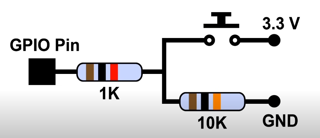
I settled on these buttons from Digi-Key. They have an OK key-feel, but are great for the price, and come in lots of different colors. They also slot into a breadboard for easy prototyping.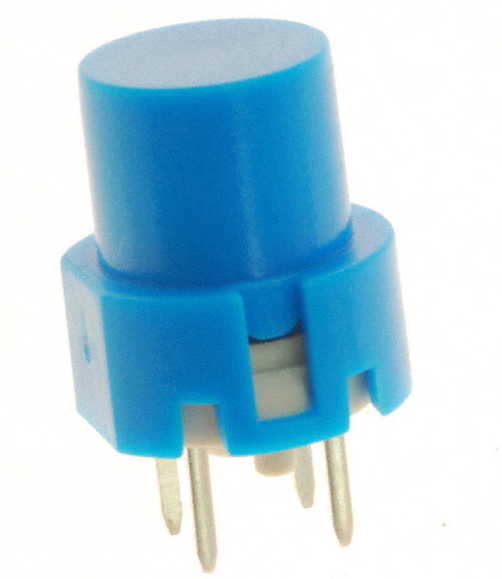
Everything was looking good though the sound coming out of the Pi was low. I could hear it in my quiet workshop, but organs are supposed to be loud.
Op Amp Woes
Forrest Mims has a whole section in the book on the operational amplifiers. I quickly wired up his suggested circuit in an attempt to get more sound out.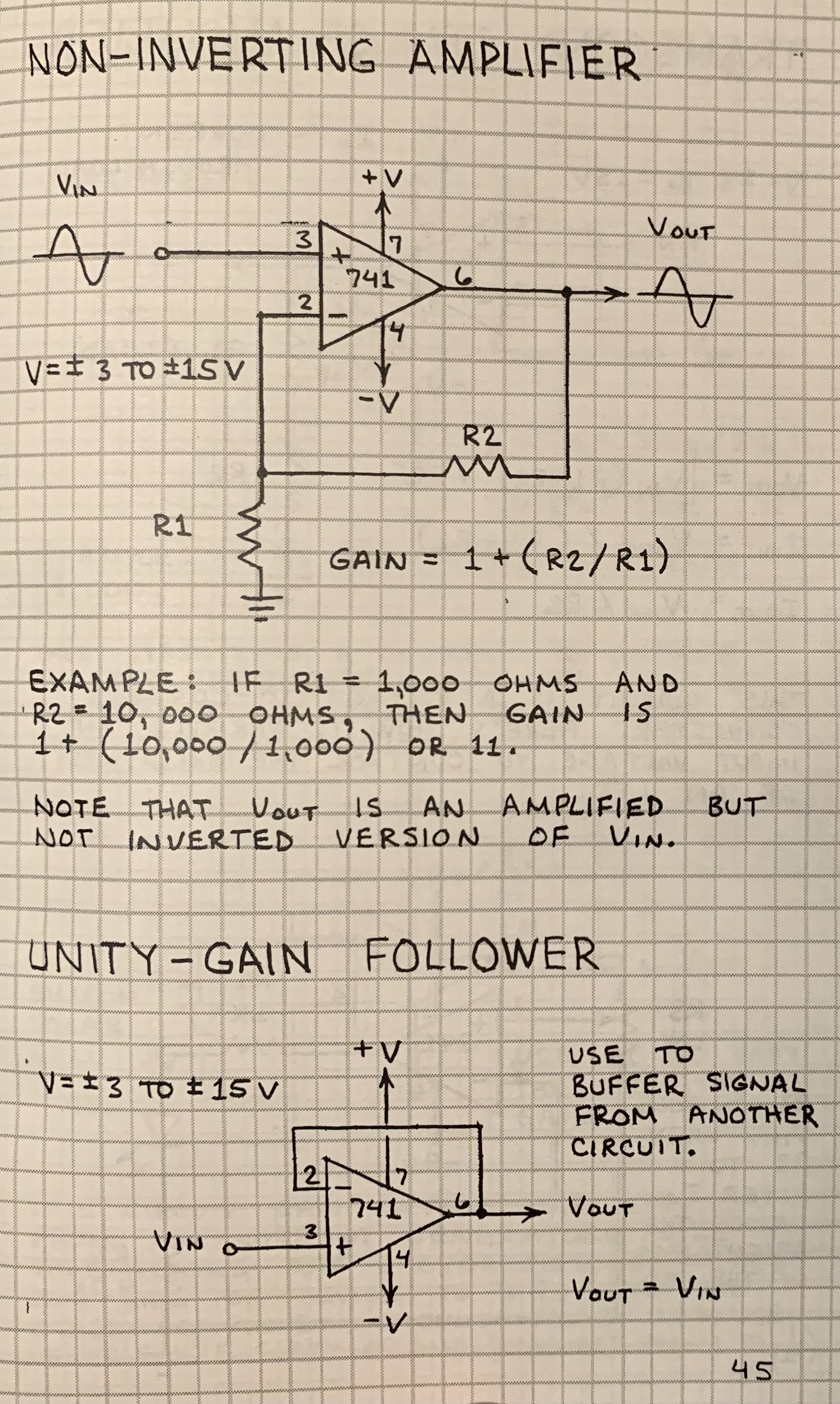
The sound coming out was faint and distorted. I tried swapping out resistors and it didn’t help. Reading a bit on forums, I learned that the 741 isn’t meant for modern use. A more contemporary IC is a TLC271ACP or similar. I bought one from Digi-Key, and updated my circuit. It had the same problem as the 741. Reading a bit more I’ve learned that using these Op-Amps requires careful adjustment of the variable resistor.
I remembered from my Arduino days the TIP120, and a quick google search popped up Adam Meyer’s blog where he has a great post on how to use a TIP120 to amplify your microcontroller’s output. Basically, you just have to make this circuit: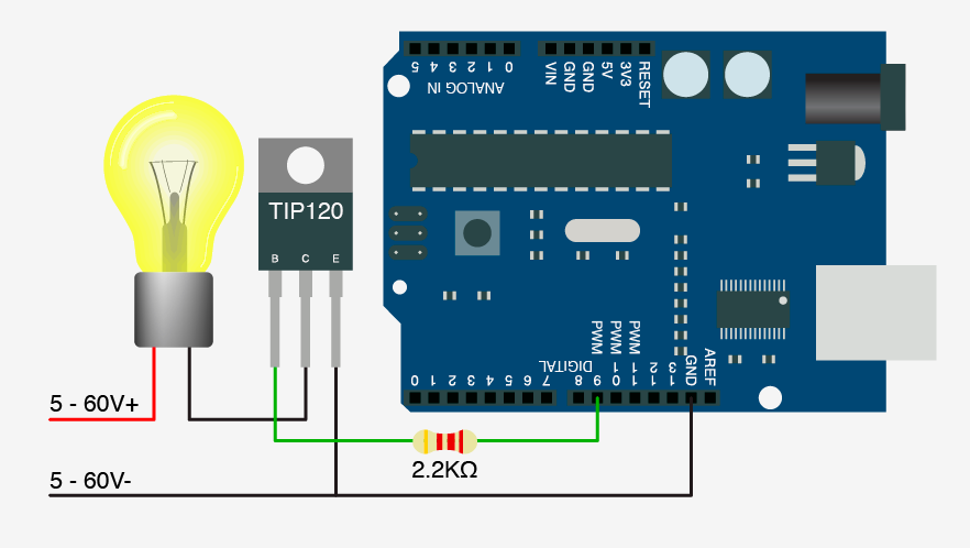 After quickly making the circuit, and playing around with resistor sizes, it worked great! I would recommend this speaker by Adafruit. Very solid and loud.
Final Version
Here’s a video of the working Toy Organ.
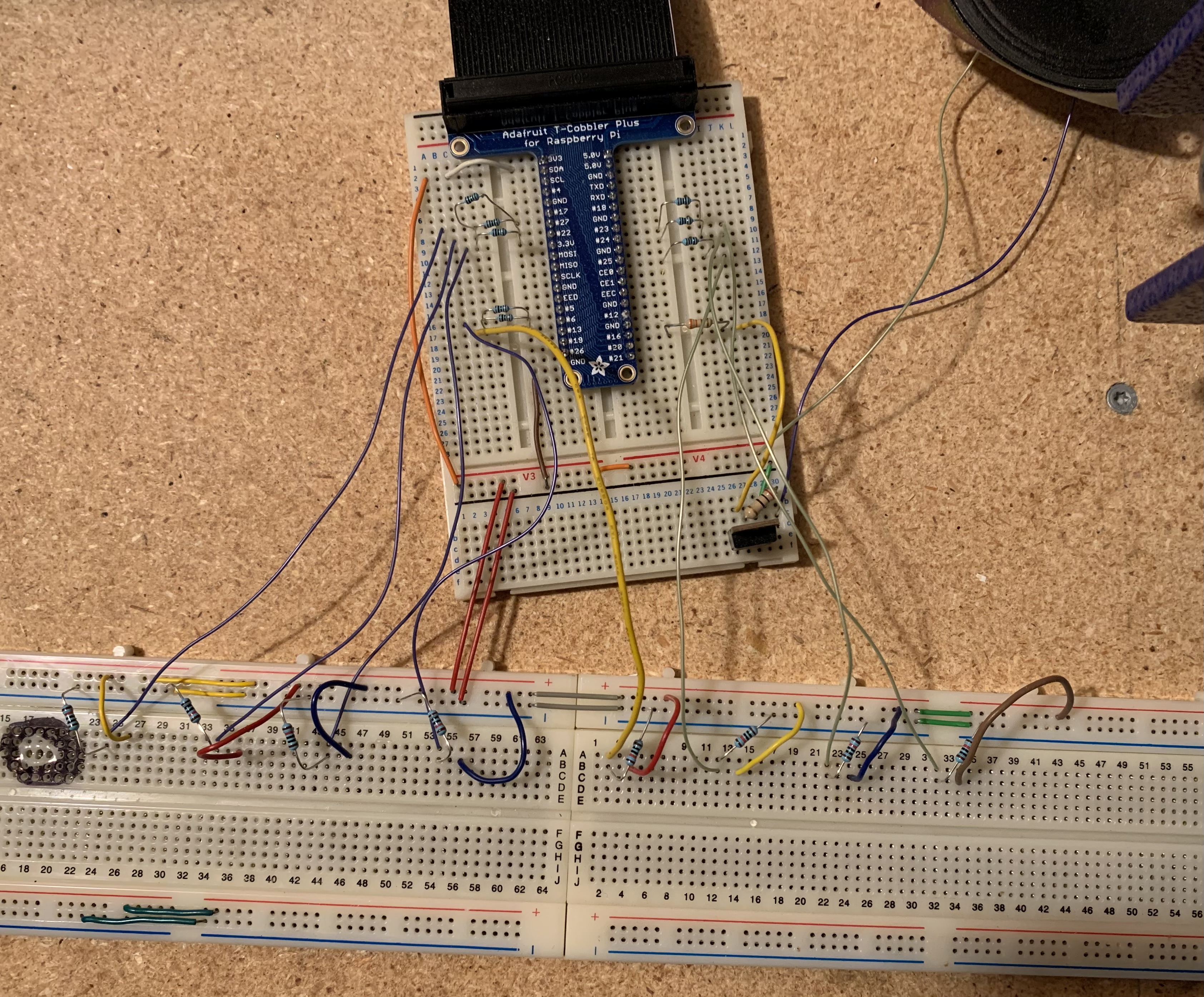
Here’s an overview photo of the wiring. My son removed the buttons.